
Such feature histories cannot be completely interpreted when a 3D model is brought in directly from one CAD format to another.
#Solid edge cad kernel update
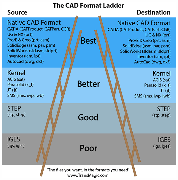
The feature-based design approach involves a history tree and a well-structured methodology of creating constraints that assure changes made to a design will also update the related parts or subassemblies. The final model will have the quality and precision of the least accurate system in the translation chain.ĭesign Approaches to Solve Interoperabilityĭirect modeling, PTC Creo Direct. The quality or richness of existing 3D models also depends on the number of times a model is exchanged or converted. These three neutral formats are supported by almost all CAD systems. From a designer’s perspective, it is advisable to use DWG or DXF for 2D drawings, IGES for surfacing and STEP for exchanging solid geometry. Each CAD-neutral format is very different and has its own value and strength for specific applications. Converting native files to a neutral format also commonly results in geometric errors, tolerance issues and loss of metadata associated with the design. Although every designer would prefer a universal CAD format, the issue with neutral formats is that, to some extent, they strip off much of the rich data embedded in the native CAD format.

However, this complexity can result in a closed, proprietary file format absolutely incompatible with other CAD systems.ĭesigners heavily use IGES, STEP, STL and JT Open for exchanging files in a neutral format. Such rich design and manufacturing details embedded in the 3D model are valuable across the entire life cycle of a product. They now encompass rich data such as material information, styling, annotations, manufacturing process data, cost and hooks as well as other features across the design files, including product structure. Over time, CAD systems have evolved to include more than just geometric and dimensioning information in 3D models. The ability to seamlessly exchange various CAD formats directly impacts a project’s schedule. In such cases, the large manufacturers historically impose requirements on their suppliers to work with their chosen CAD system or format. Larger automotive and aerospace manufacturers, in particular, tend to continuously face the issue of working with multiple CAD formats for different projects across their entire supply chains. Other factors include cost, retraining or maybe even a policy to not rely on a single vendor. plastics, sheet metal design, styling, etc.). Sometimes a company chooses a secondary CAD vendor that offers specialization in certain areas (i.e.

For instance, a company may have a history of mergers and/or acquisitions of other companies that have resulted in a mix of CAD platforms. Manufacturers cite various reasons for using multiple CAD vendors.
#Solid edge cad kernel software
Compounding the problem, most manufacturing firms, on average, use at least three different CAD software products for their product design needs. Each 3D CAD model springs from an underlying mathematical kernel that created it, and each will interpret geometry differently. Opening a 3D CAD file designed in one vendor’s CAD in another system without a format conversion process has historically resulted in inconsistent or sometimes broken geometry and loss of design intent.


 0 kommentar(er)
